1. Add 33 ohm (0201) resistors on the back of the board (R176-R203)
Incase these are not available add zero ohm resistor or simply solder across the resistor pads.
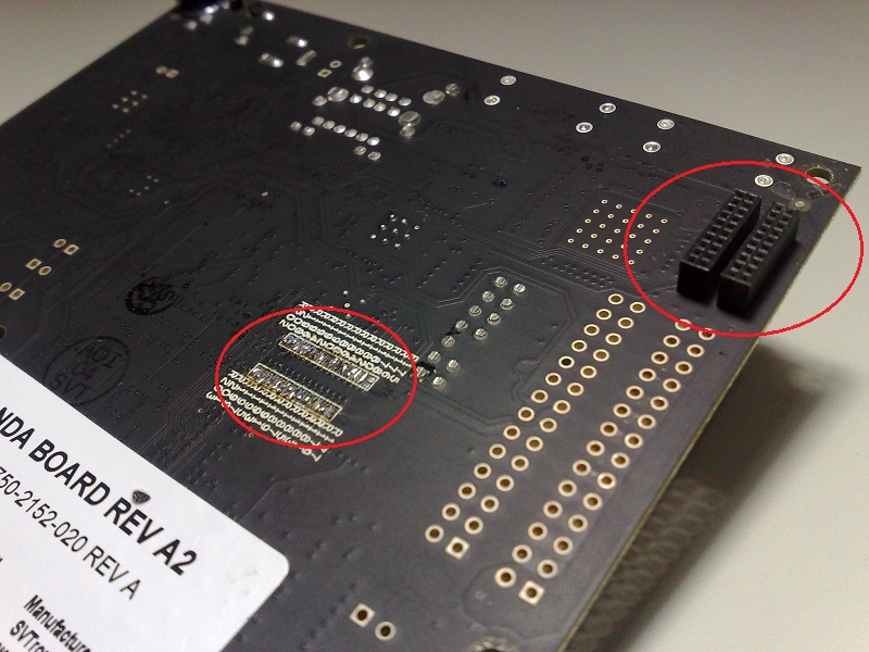
2. Mount J1&J4 on back of the board
Actually solder them on top side.
Pandaboard reworks of connecting to BeadaFrame display
Re: Pandaboard reworks of connecting to beada frame display
Pandaboard ES has a different schema(resistor array instead of resistor series) for LCD signal routing, than Original Pandaboard.
I will post an update for that soon.
Re: Pandaboard reworks of connecting to beada frame display
This is all for pandaboard ES rev. B LCD hardware configuration.
esky-sh wrote:Pandaboard ES has a different schema(resistor array instead of resistor series) for LCD signal routing, than Original Pandaboard.
I will post an update for that soon.
Re: Pandaboard reworks of connecting to beada frame display
it should be on bottom. so you will need to remove the black plastic standoffs.
LARDEUR wrote:solder connectors J1 and J4 must be made on the top and bottom or only just bottom suffice?
Who is online
Users browsing this forum: No registered users and 31 guests